
An upright sprinkler sends water upward against a deflector above its outlet. A pendent sprinkler sends water downward against a deflector below its outlet. The deflector then shapes the water distribution over the protected area. Turning one head upside down does not turn it into the other type.
Upright vs. pendent sprinkler heads differ in the direction of the initial water stream and their relationship to the pipe and ceiling. Flow capacity, thermal response, operating temperature, and freeze protection are separate selection characteristics.
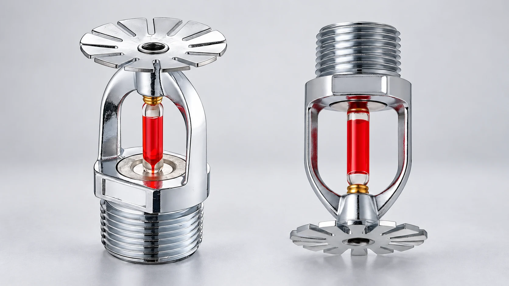
How Each Orientation Directs Water Through the Deflector
In a closed automatic sprinkler, a heat-sensitive element holds the outlet closed until operation. Depending on the design, that element may be a glass bulb or a fusible link. Water enters through the threaded inlet, passes through the outlet when the sprinkler opens, and strikes the deflector supported by the frame. The deflector’s shape and position are part of the sprinkler’s distribution design.
NFPA describes this relationship between the water stream and deflector in its explanation of sprinkler types and orientations. The upright and pendent names identify the initial stream direction; each deflector then forms the spray over the protected area.
Upright: Water Rises to the Deflector
An upright sprinkler has its threaded inlet below the frame and its deflector above the outlet. After the thermal element releases the closure, water travels upward through the outlet and strikes the underside of the deflector. The deflector redirects and breaks up that stream to distribute water outward and downward into the protected area.
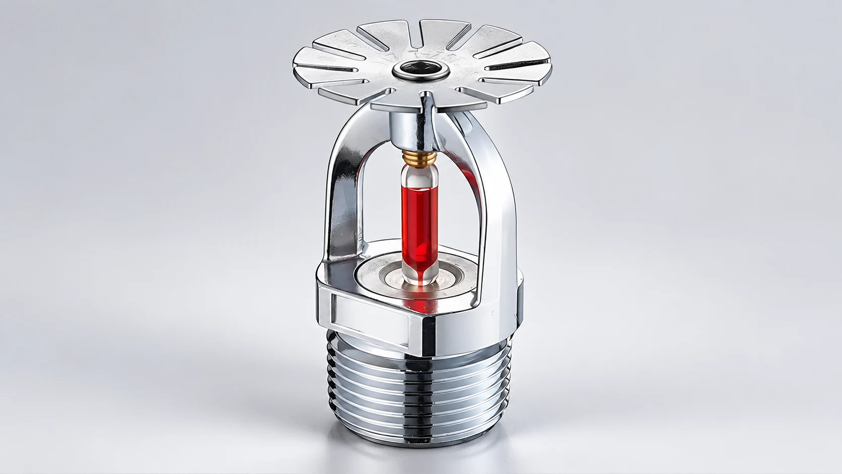
Upright heads are common above exposed branch lines or on short vertical extensions called sprigs. That arrangement can suit open-ceiling spaces where the piping and head remain visible.
Pendent: Water Flows Down to the Deflector
A pendent sprinkler has its threaded inlet above the frame and its deflector below the outlet. Once the outlet opens, water travels downward to the deflector, which spreads the stream into the sprinkler’s designed distribution. The thermal element and frame sit between the inlet end and the deflector. Their arrangement, together with the deflector geometry, belongs to that head’s specified downward orientation.
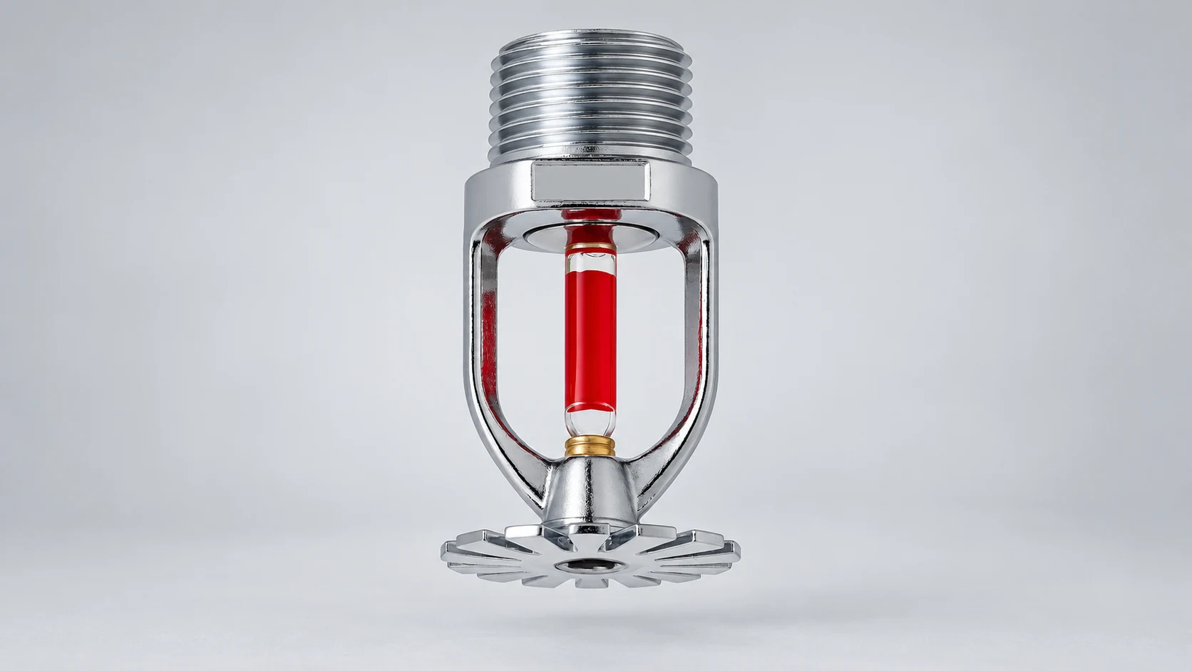
Pendent heads commonly project below a ceiling or connect to piping through a downward drop. This places the deflector below the pipe connection, but a pendent head can also be exposed in an open-ceiling space.
Compare Pipe, Ceiling, and Obstruction Geometry
The outlet, deflector, pipe, and surrounding construction form a single spatial arrangement. Compare the two orientations on the same dimensions:
| Comparison | Upright | Pendent |
|---|---|---|
| Specified orientation | Deflector above the outlet; inlet below the frame. | Deflector below the outlet; inlet above the frame. |
| Initial water path | Upward into the deflector, which forms the distribution. | Downward into the deflector, which forms the distribution. |
| Common pipe and ceiling relationship | Above exposed branch piping or on a sprig, often in an open-ceiling space. | Below the pipe connection, often on a drop to or through a ceiling. |
| Space and obstruction checks | Check the deflector’s position relative to the ceiling and nearby beams, pipes, equipment, and other obstructions. | Check the deflector’s position relative to the ceiling and nearby beams, pipes, equipment, and other obstructions. |
| Performance information still needed | Model-specific coverage, application, response, temperature, K-factor, and listing conditions. | Model-specific coverage, application, response, temperature, K-factor, and listing conditions. |
Consider an exposed branch line beneath a beam. An upright head places the deflector above the connection, making the space between the pipe, beam, and ceiling relevant. At a finished ceiling served by a drop, a pendent head puts the deflector below the connection, so the drop length and ceiling detail determine where the deflector sits.
A beam, duct, pipe, or piece of equipment can intercept water traveling from the deflector into the protected area. The head’s location relative to that obstruction matters alongside its orientation. Deflector clearances and obstruction rules apply to the actual ceiling and piping geometry.
Recessed and concealed describe ceiling assemblies and trim arrangements. Our recessed vs. concealed sprinkler comparison explains the difference between a visible trim ring and a cover plate.
How K-Factor, Connection, and Orientation Work Together
The K-factor is the discharge coefficient in the flow relationship Q = K√P. In U.S. units, Q is flow in gallons per minute (gpm), P is pressure at the discharging sprinkler’s orifice in pounds per square inch (psi), and K has units of gpm/√psi. This relationship appears in NIST’s NCSTAR 1-4B report, Equation 6-1.
At a pressure of 25 psi at a discharging sprinkler’s orifice, K = 5.6 gpm/√psi gives a calculated flow of Q = 5.6 × √25 = 28 gpm. Water-supply static pressure is measured before discharge; the pressure available at a flowing sprinkler also reflects the system’s pressure losses. The calculated 28 gpm describes flow, while the deflector and its position determine how that water is distributed.
Upright and pendent heads can share a K-factor of 5.6 gpm/√psi and a 1/2-in. NPT connection. At equal orifice pressure, their calculated flows are equal. The 1/2-in. NPT designation describes the nominal connection. Each head still uses a deflector designed for its own stream direction: upward into the upright deflector or downward into the pendent deflector.
That separates three parts of a replacement match: K-factor relates flow to pressure, the thread provides the connection, and the specified orientation places the deflector in its intended water path. A head turned upside down changes that path even when the connection fits.
Select Response, Temperature, and Freeze Protection Separately
Response and Temperature Are Different Characteristics
The response time index, or RTI, characterizes how a sprinkler’s heat-responsive element reacts to heating. NFPA’s explanation of sprinkler thermal characteristics identifies fast-response elements as having an RTI of 50 (m·s)1/2 or less and standard-response elements as having an RTI of 80 (m·s)1/2 or more. Quick-response sprinklers are one type within the fast-response group. RTI measures thermal sensitivity rather than a delay of 50 or 80 seconds before operation.
The nominal operating temperature is a separate rating. NFPA’s table places ordinary-temperature nominal ratings in the range 135–170°F (57–77°C), paired with a maximum ambient ceiling temperature of 100°F (38°C). The rating describes the sprinkler’s thermal element; the ambient value describes the air around it at ceiling level. In this table, a 135°F nominal rating belongs with the 100°F ambient limit, keeping normal ceiling heat below the element’s operating temperature.
Two heads can have the same nominal operating temperature and different response classifications. Ceiling height, sprinkler location, ambient temperature, and fire exposure also affect actual operation. Orientation describes the water path; RTI and nominal operating temperature describe the thermal behavior.
How Freeze Protection Works
Freezing depends on where water remains and the temperatures it encounters. An upright orientation can avoid the downward water pocket associated with some piping arrangements. Water-filled piping exposed to freezing can still freeze, so drainage and system configuration remain part of freeze protection.
A dry-type sprinkler uses an inlet seal to keep water out of its extension until the sprinkler operates. This construction holds the water back from the exposed extension and addresses a different problem from directing the discharge upward or downward.
Poseidon’s fire sprinkler head range provides the product-family starting point. The pendent sprinkler head page covers the downward-facing option.